Introduction
The UV Editor is used for editing UV maps, which describe how a 2D image should be mapped onto a 3D object.

UV Editor with a UV map and a test grid texture.
Image textures are typically needed when the desired look is hard to achieve with procedural textures, or if the texture is not uniform. For example, a car would only have scratches in a few places where they make sense, not in random places all over its body.
Blender offers a number of projections (Box, Sphere…) that automatically apply a 2D image to a 3D object, but these tend to only work for simple meshes. For more complex ones, you need to create a UV map instead. This is a flat area where each face of the 3D object is laid out on the 2D image, specifying which part of the image it should be textured with. This gives you complete control over the mapping process.
The name “UV” refers to the axes of the map: U for horizontal, V for vertical. These letters were chosen to avoid confusion with “X” and “Y”, which refer to axes in 3D space instead.
UVs Explained
The best analogy to understand UV mapping is cutting up a cardboard box. If you were to take a pair of scissors and cut along its edges, you would be able to spread it out flat on a tabletop. As you are looking down at the table, we could say that U is the left-right direction, and V is the up-down direction.
As a next step, you could put the spread-out box on top of a poster, cut the poster to match its shape, glue the poster to the box, and finally reassemble the box. You now have a 3D box textured with a 2D image.
A UV map describes how the box is cut up, and how it’s laid out on the poster. You have complete freedom in how to do this: if you wanted to, you could cut each individual side of the box and position, rotate, scale, and even skew it on the poster independently of the other sides.
Example
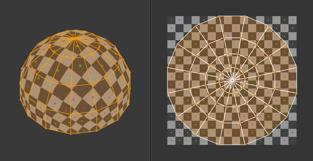
3D space (XYZ) versus UV space.
In the above image, a dome in 3D space is flattened into a disc in UV space. Each 3D face is then textured with the part of the image it covers in the UV map.
The image also demonstrates a common problem in UV maps: distortion. Notice how, even though the checkered squares in the 2D texture are all the same size, they get different sizes when applied to the 3D dome (they’re smaller at the base than at the top). This is because the faces in the UV map have different relative sizes than in 3D space, which is a result of the flattening process.
You’ll typically want to minimize this distortion by manually guiding and tweaking the flattening, using seams for example. However, it’s not always possible to eliminate it completely.
Interface
Header
UV Editor header.
The header contains several menus and options for working with UVs.
Sync Selection
Synchronizes the selection between the UV Editor and the 3D Viewport. See Sync Selection for more details.
Selection Mode
The UV element type to select. See Selection Mode for more details.
Sticky Selection Mode
Which other vertices to select automatically. See Sticky Selection Mode for more details.
View
Tools for controlling how the content is displayed in the editor. See Navigating.
Select
Tools for selecting UVs.
Image
Tools for opening and manipulating images. See Editing.
UV
Contains tools for Unwrapping Meshes and Editing UVs.
Pivot Period
See Pivot Point.
Snap Shift-Tab
See Snapping.
Proportional Editing O
See Proportional Editing.
Image
A data-block menu used for selecting images. When an image has been loaded or created in the UV Editor, the Image panel appears in the Sidebar region.
Image Pin
When enabled the current image remains visible regardless of the object selection. This switching only happens if the 3D Viewport is in Edit Mode or Texture Paint Mode.
This can be useful to enable when an image is used as a reference.
Show Gizmo
Lets you show/hide all gizmos using the toggle button, or specific gizmos using the drop-down arrow.
Navigate
Enable/disable the gizmos used to pan or zoom the 2D viewport. See Navigation Gizmos for more information.
Show Overlays
Lets you show/hide all overlays using the toggle button, or specific overlays using the drop-down arrow. See Overlays.
Active UV Loop Layer
Select which UV map to use.
Display Channels
Select what color channels are displayed.
Color & Alpha:
Enables transparency and shows a checkerboard behind the image.
Color:
Displays the colored image, without alpha channel.
Alpha:
Displays the alpha channel as a grayscale image. White areas are opaque, black areas are transparent.
Z-Buffer:
Displays the depth from the camera, from Clip Start to Clip End, as specified in the Camera settings.
Red, Green, Blue:
Single color channel visualized as a grayscale image.